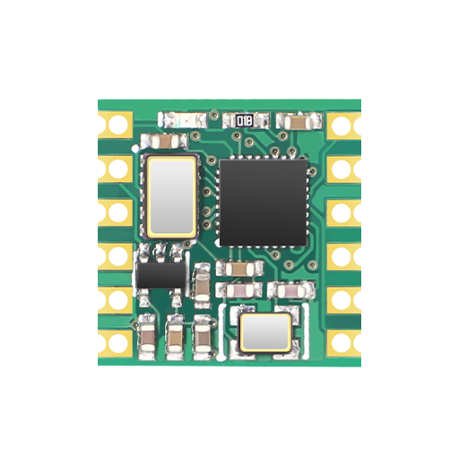
Guide to Connecting Module Type Sensors: Wiring, Interfaces, and Supported Models
name | I/O type | function |
D1 | I | GPS data receiving pin, connected to GPS TX |
D2 | O | Hardware reset port |
Difference Between TTL, RS-232, RS-485, and CAN Levels Explained
Product selection issues:
What is the difference between TTL, 232, 485 and CAN levels?
TTL, 232, and 485 are different level standards for serial ports. TTL is commonly used for direct connection of microcontrollers. The connection is simple and convenient but the transmission distance is short. 232 or 485 levels are commonly used in industrial environments. The CAN interface can be networked and is often used in complex industrial environments. The transmission is reliable but the cost is high.
level
|
Recommendation line length
|
signal type
|
Transmission direction
|
Recommended usage environment
|
Remark
|
TTL
|
Within 1 meters |
Level signal: susceptible to interference |
full duplex |
Microcontroller connection |
Need to share ground |
RS232
|
Within 10 meters |
Level signal: susceptible to interference |
full duplex |
industry
|
Need to share ground |
RS485
|
Within 100 meters |
Differential signals: less susceptible to interference |
half duplex |
industry
|
No need to share ground for short distances |
CAN
|
Within 200 meters |
Differential signals: less susceptible to interference |
half duplex |
car bus |
No need to share ground for short distances |
Troubleshooting Common Issues with Attitude Sensor Data Recording
Data related issues
1. Why do the data recorded by the attitude sensor host computer repeat at a high return frequency?
The data recorded by the attitude sensor host computer at a high return frequency will be repeated. This is because although the data output rate of the attitude sensor is high, the internal data is faster.
The new rate is not that high. The solution is to set the bandwidth higher, so that the sensor data inside the attitude sensor will be updated faster, and it will
Reduce data duplication.
2. Why is the data of the attitude sensor inaccurate when the Y-axis is close to 90 degrees?
When Euler angles represent postures, there will be a singularity phenomenon, and the location of the singularity is related to the rotation sequence of Euler angles. For example, the rotation sequence of Euler angles is defined as Z-Y-X, then
The Y axis ±90° is the singular point position. If the rotation sequence is defined as Z-X-Y, then the X-axis ±90° is the singular point position. Our modules are defined according to Z-Y-X. This is okay
To understand, the Z-axis represents the direction angle, which is equivalent to the direction of the X-axis. When the Y-axis is 90 degrees and X points upward, the Z-axis represents the same posture at any angle. There is no
significance. Also, assume that the X-axis is 0 degrees and the Z-axis is 0 degrees. The Y-axis changes from 89° to 91°, and the posture will change from [0, 89, 0], [180, 91, 180], and the X-axis angle
The degree has mutated from 0 to 180°, and the Z axis has also mutated.
3. Why do the data recorded by the attitude sensor host computer repeat at a high return frequency?
The data recorded by the attitude sensor host computer at a high return frequency will be repeated. This is because although the data output rate of the attitude sensor is high, the internal data is faster.
The new rate is not that high. The solution is to set the bandwidth higher, so that the sensor data inside the attitude sensor will be updated faster, and it will
Reduce data duplication
4. Why is the magnetic field data of the attitude sensor inaccurate?
The inaccurate magnetic field data of the attitude sensor may be caused by the failure of magnetic field calibration or related to the use environment. You can try to solve the problem of inaccurate magnetic field data of the attitude sensor from the following two points.
The problem:
1. Calibrate the attitude sensor.
Calibration steps: Connect to the host computer, click to start calibration. When the host computer returns an OK, start the calibration (the module rotates horizontally for about two weeks), and then click
Click to end the calibration, and the host will return an OK.
2. Check whether there is iron or magnetic interference in the usage environment, and stay away from iron and magnets when using the attitude sensor.
Note: When calibrating, you need to stay at least 20cm away from magnets or iron.
5. Why does the attitude sensor angle data keep changing?
The horizontal data is unstable, usually because there is no additive calibration. If the nine-axis Z-axis data is inaccurate, it is usually due to interference in the magnetic field, or the magnetic field is not calibrated or not calibrated.
It‘s not good. If it is 6 axes, the z-axis data changes greatly, which means the cumulative error will be large.
6. Why does the Z-axis of the attitude sensor have 1 g data?
After the sensor is placed horizontally and the acceleration is calibrated, there is still 1 g data. This 1 g is the acceleration of gravity. According to the axial direction, the Z-axis points upward, and the module is static.
Stop, the acceleration of gravity points downward, so there is a force with the same magnitude as the acceleration of gravity pointing upward, so there is data of 1g (positive direction).
7. Why is the file data recorded by the attitude sensor host computer so messy?
The attitude sensor host computer record file data is very messy, which may be caused by the following reasons:
1. If the file data recorded by the host computer is completely messy, check whether the host computer is the latest version. If not, you can ask our customer service for the latest version of the host computer.
machine.
2. If the file data recorded by the host computer is a txt file and the data is not aligned left and right, it is because the tab characters in Notepad are not aligned, not the host computer.
8. Why does the attitude sensor host computer have no data?
The solution to the problem that the attitude sensor host computer has no data is as follows:
1. Confirm the wiring and carefully check whether the wiring is correct according to the instructions.
2. Check whether the baud rate is correct and whether the serial port is open.
3. Check whether the wiring is reversed. If it is reversed, the attitude sensor may be burned out. This situation is irreversible damage and requires a new attitude sensor.
Guide to Calibration Techniques for Accurate Angle and Magnetic Field Measurements
Acceleration, angle and magnetic field related problems
1. Angle problem
The product measurement angle is Euler angle. The rotation sequence of Euler angle is ZYX sequence. If you need to get a fixed angle, you need to rotate each axis in this sequence, so that you can get the Euler angle. The definition of the four elements is W XYZ The definition of can be used to calculate Euler angles.
2. Addition calibration
Additive calibration is to set a measurement reference coordinate system for the product. The angle measured after horizontal calibration is the angle with the horizontal as the reference.
Adder calibration method: Place the module horizontally (with the logo facing up, if it is a module, the side with the chip faces up), then click on the host computer to configure acceleration calibration or main adder calibration, and the light strip will take about 5 seconds. The totaling calibration can be completed. After success, the XY angle will be close to 0 degrees. If there is no effect, repeat the calibration.
3. Magnetic field calibration
The Z-axis of the nine-axis product is calculated using a magnetic field, and it conforms to the northeast sky coordinate system when there is no magnetic field interference. When does it need to be calibrated? That is, the actual angle of rotation does not match the angle displayed by measurement and the error exceeds 10 degrees, that is, the angle is inaccurate and needs to be calibrated.
4. Six-axis sensor heading angle error problem
The six-axis sensor does not contain a magnetic field meter. There is no magnetic field observation to filter the yaw angle. Therefore, the yaw angle is calculated through pure integration. There will inevitably be drifting phenomena. Intelligent realization of rotation angle measurement in a short time. The X·Y axis angle can be filtered and corrected through the weight field without drift.
Posture expression method and conversion
1. Euler angles and quaternions
1.2 Euler angle 321 to quaternion
1.3 Quaternion to Euler angle 321
2. Relative attitude algorithm
2.1 Quaternion relative posture
2.2 Euler angle relative attitude
1. First convert the two Euler angles into quaternions
2. Calculate the relative quaternion again
3. Let’s talk about converting quaternions into Euler angles
3. Euler angles and rotation matrix
3.1 Quaternion to rotation matrix
3.2 Euler angle 321 rotation rotation matrix
Euler angle to rotation matrix Python code
Sales Director : Shirley Hou
E-Mail: h@mice-yun.com
Mob / Whatsapp: +86 188 0664 3732